Air Valve Technology a Critical Review
The need for adequate, total and efficient pipeline performance has become more critical in recent times. This is due to the growing shortage of experienced maintenance teams, the increased focus on sustainable infrastructure development and the focus on Life Cycle Costing and pipeline efficiencies.
Air valves are amongst the most cost-effective components on pipelines and play a major part in attaining optimum pipeline performance but if incorrectly selected, sized and positioned, are the root cause of many destructive pipeline phenomena.
In 1996, the author wrote a booklet titled “Air Valve Technology Reviewed” which briefly covered a 35 year period of air valve history and the technologies that developed in the quest for a cost-effective solution to air release and the Surge and Waterhammer phenomena
The book highlighted that technology is not stagnant but advances as research improves and as the focus on specific pipeline phenomena increases. This is evident by the number of technical papers and research studies with a specific focus on air release from pipelines and the potential impact of Surge and Waterhammer that have proliferated since the authoring of this document 16 years ago.
Interestingly, as much as air valve research and technology have advanced, so have the older air valve technologies still remained in constant use. This has resulted in a global market that has a spread of air valve technologies with the preference for a specific technology based on historical factors, and market dynamics but not always necessarily based on access to the latest research and pipeline performance criteria. This peculiarity is also reflected in the South African market.
It has become an expected norm for air valves to perform four functions namely; pressurised air discharge when the pipeline is operating, large volume discharge during initial filling of the pipeline, large volume air intake when the pipeline drains and automatic Surge protection when air is released too rapidly or, under pump trip conditions.
Of all the air valve functions, the area that attracts the most attention is the Surge protection function. This article covers the evolution of Air Valve Technology in South Africa from 1995 to present with a specific emphasis on automatic Surge protection in air valves.
A Brief Background to the Problem of Surge and Waterhammer Induced by Air Valves
Air Valves are most commonly located at high points along a pipeline where they prevent cavitation in the pipeline by introducing large volumes of air into the pipeline under drainage conditions and are generally sized firstly for air intake conditions.
However, this implies that the Air Valve orifice may be too large under air discharge conditions. Rapid discharge of air from too large a discharge orifice relative to the pipeline diameter results in high pressure transients (waterhammer) because of the rapid deceleration of the water at the instant the air is fully expelled. This produces a pressure transient similar to the rapid closure of an isolator valve along the length of the pipeline.
The magnitude of transients created in this manner is dependant on several variables including the pipe material, the pipeline profile, the bulk modulus of the water, the velocity in the pipeline, the number and spacing of the Air Valves, the length of the riser towards the air valve, the ratio of the air valve outflow area to the main pipeline diameter at the point of final discharge and the manner in which the Air Valve is constructed.
Manufacturers have over the years been challenged to develop air valves that balance the need for large volume air intake but controlled and efficient air discharge whilst accommodating for all these variables to protect both the Air Valves and pipelines from the damaging effect of Surge and Waterhammer as a result of air release. The challenge has been made greater by the complexity of air release and the unpredictability of pipeline operation. All of these factors combined affect the efficacy of any air valve’s surge protection device.
Several Air Valve technologies with inherent automatic surge protection devices have proliferated in the last 16 years. Available currently on the South African market are six different Air Valve designs, four of which have inbuilt Surge protection devices. Each of these designs are touched on below.
Non Return Air Valves (Vented Non Return Air Valves)
One of the 1st credible solutions to surge protection, utilising Air Valves, was the development of Non Return Air Valves. This technology has been available for more than 50 years. There are several different designs from the USA and Europe and the UK. With the European and UK technologies often termed Vented Non Return Air Valves. All these valves operate similarly.
These valves allow unrestricted air intake during column separation but control air discharge as the column rejoins, thereby limiting the possibilities of water hammer from occurring.
However, releasing air only through a small orifice can lead to liquid oscillation (Surge pressures) as the rejoining water column tends to compress the large volume of air rapidly; faster than the small orifice can release the air. The entrapped air will act as a spring, causing the liquid to oscillate in the pipeline system. In addition, pipeline filling is substantially delayed due to the dependence of air release from a very small orifice.
A frequent recommendation by maintenance and installation crews is to bleed the air manually through the Air Valve isolator when filling the pipeline then install the air valve afterwards. This allows for more rapid pipeline filling but substantially increases the installation and/or pipeline maintenance costs.
Consequently, the benefit of this technology is only for severe peak points where the size of the orifice will have to be carefully selected for the application. This restricts flexibility in design.
Non Return Air Valve technology imported from France was utilised for many years on bulk water pipelines as part of an earlier surge protection strategy in South Africa but was replaced in the late 1990’s by local technologies. However, Non Return Air Valve technology has been re-introduced into South Africa not necessarily based on any technological advantages it provides but as part of a supplier’s package offering. Currently this technology originates from the UK with similar local alternatives.
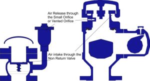
Fig 1. Non Return Air Valves/ Vented Non Return Air Valves – Two different designs of Non Return Air Valves. Both valves behave similarly in that air is introduced into the valve under vacuum conditions but discharged through a smaller orifice under pump trip conditions. The valve may release air too slowly resulting in mass oscillation.
Three Stage (Anti Shock or Anti Slam) Air Valves
An approach to Surge protection utilising air valves first proposed in 1983 is to release a predetermined amount of air from a large orifice and then release a smaller volume of retained air in a controlled manner through a smaller orifice thereby ensuring rapid filling of the pipeline whilst limiting potential Surge or Water hammer. This proposal was put forward in a seminal technical paper outlining practical case studies on a large diameter pipeline in Saudi Arabia.
The optimum balance between the size of the outlet orifice and the amount of air released before switching to a smaller orifice can result in the reduction of mass oscillation as well as water hammer whilst ensuring effective air release.
The device proposed in 1983 whilst effective was extremely cumbersome and expensive as it consisted of five valves and a complex configuration of fittings. Technologies achieving similar results were developed independently in 1980 in the UK and in 1988 in Japan. A cost effective, compact device that imitated some of the results achieved by the practical studies highlighted in the 1983 technical paper first appeared in the South African market in 1994.
This technology has become known as three stage Air Valves as it generally consist of three orifices namely; a large orifice for large volume air discharge or intake, a small orifice for pressurised air discharge and a floating intermediary orifice that will at a specific differential pressure be lifted to seal off the large orifice thereby releasing air through a smaller port which creates a back pressure to slow down the advancing water column, limiting surge and waterhammer when the water enters the air valve. These air valves are also known as Anti Shock or Anti Slam air valves.
This design concept works effectively if the differential pressure created is high enough to lift the floating orifice to seal off the larger outlet but will create waterhammer if the correct differential pressure is not achieved.
Parameters such as the size of the pipeline, the flow velocity within the pipeline and the size of the valve influence the shear mass of the floating orifice which increases the switching point of the orifice. The higher the switching point, the greater the potential for damaging surge and if the switch does not occur then, the valve can create slam (waterhammer) on closure.
Additional factors to consider for the design engineer when using this design is the spacing between valves – if two or more valves are too closely spaced together then the possibility exists that the valve adjacent to the flow may switch into the anti slam mode whilst the valve further away may have insufficient air to do so before the water flow reaches it, resulting in it creating waterhammer on closure.
Anti Slam or Anti Shock type air valves have static orifice diameters. There is a possibility that the orifice diameter of the anti slam device may be too large resulting in air being released too rapidly, thereby creating Waterhammer or too small thereby creating mass oscillation (surge) in the pipeline.
The two stage switching and the combination of the amount of air being released initially versus the switching point and the size of the anti slam orifice can create Waterhammer in applications such as Air Valves subsequent to the pump, Air Valves prior to the non return valve in a borehole application and Air Valves at the peak points of steep slopes. Because of these limitations, certain manufacturers often specify Air Valves with a bias mechanism that functions similarly to Non Return Air Valves at critical points along the length of the pipeline.
There are currently three manufacturers of Anti Slam or Anti Shock air valves in South Africa. Though the design configuration of these valves differs, their surge protection functions are similar.
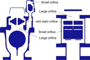
Fig 2. Three Stage Anti Slam Air Valves – Two different designs of Three Stage Air Valves indicating the three orifices which operate at stages of the valves’ operating cycle. These designs are also known as Anti Slam or Anti Shock valves.
Anti Slam Air Valves with Slow Closing Mechanism
Among the many American, Air Valve technologies that have evolved is one that has been around since the late 1950’s which normally has a perforated non return valve disc positioned underneath the Air Valve. This allows for the Air Valve to release air but when water enters, it lifts the non return valve disc and water slowly enters the air valve chamber thereby preventing a slam in the valve chamber when the floats are buoyed to close the outlet orifice.
This technology has been duplicated in a recent South African air valve design which combines the functions of an Anti Slam – three stage air valve with a slow closing mechanism.
The South African designed valve will draw in air under vacuum conditions and discharge air as the water columns commences to rejoin. Air will pass unrestricted through the valve but will switch to a smaller outlet once a specific differential pressure is reached. In this respect, the design operates on much the same principles as other anti slam devices.
The reduction in orifice diameter is achieved in a chamber prior to the control float chamber by the lifting of the regulator floats. When water enters the Air Valve, the passage of water through the valve will therefore also be throttled. The control float is moved to a closed position by the water which enters the valve at a reduced rate. This aspect of the design is similar to the older American technology.
The valve design is such that the regulator floats mass can be increased or decreased to influence the switching point from a large to a smaller discharge orifice. However, the switching point needs to be determined beforehand and only through a surge analysis. This design has, in the manner in which the anti slam feature functions, the same drawback of a static orifice which impacts other anti-slam air valve designs.
The additional feature in this design is the cushioning benefit provided to the upper float assembly when water enters the valve due to the throttling of the flow prior to the control float.
However, should the switching point and therefore the throttling of the flow not be achieved in the presence of air, then a pressure transient can be created in the lower chamber of the valve when the floats in the lower chamber are lifted by water entering the valve. The increase in pressure is a result of water having a much higher density than air, causing the flow rate to drop as it reaches the opening, which will have a similar effect to the sudden closure of a valve at the end of a pipeline discharging water. This phenomenon is well described in experimental work conducted by researchers around the world over the past three decades or more. Research conducted by the Southern Research institute in Birmingham Alabama in the USA as far back as 1959 on a similar device, indicates that the pressure transient created on closure can still exceed more than two times the valve’s designed operating pressure.

Fig 3. Anti Slam Valve with Slow Closing Mechanism – On the left is an American design utilising a non return valve with a perforated disc to ensure that the water is throttled therefore solely entering the valve chamber. On the right is a recent South African design utilising regulator floats in a separate chamber to provide an anti slam function as well as a slow closing function.
Hydraulically (Diaphragm) Controlled Air Valves
Hydraulically Controlled Air Valve technology has been available in the USA for many years and functions the same as conventional double acting air valves except that it has an externally mounted hydraulic dashpot to control the rate at which the valve closes.
An invention that recently entered the South African market utilises the same principle of the Hydraulically Control Air Valve but utilises a diaphragm in place of dashpots to create a chamber that provides an equal pressure but differential area arrangement for the water entering the valve. Slow closure of the valve is achieved as water trickles into the chamber above the diaphragm, creating a downward force due to the large area advantage of the chamber versus the inlet of the valve.
The valve will draw in air when pump trip or vacuum conditions occurs and, will discharge air as the column commences to rejoin. Air does not have any effect on the closure of the valve during discharge as closure is controlled by adjustment of the hydraulic controls on the dashpot in the case of the USA design and as the force for closure builds up in the chamber above the diaphragm in the case of the diaphragm design. Which implies that the valve, regardless which one of the two designs, will permit the regulated discharge of water at a preset closing time.
The actual spillage of water may induce a pressure surge because water has a much higher density than air, causing the flow rate to drop as it reaches the opening, which will have a similar effect to the sudden closure of a valve at the end of a pipeline discharging water. Experimental work conducted by researchers in a number of countries including Dr. van Vuuren of South Africa indicates that the most important variables influencing the magnitude of a pressure rise for air released in this manner are; internal pressure, volume of compressed air pocket, size of opening through which the air escapes and the elasticity of the system.
The amount of water spilled before the valve closes is highly dependant on the time period for the valve to close, the differential pressure across the valve and the size of the valve outlet relative to the main pipeline.
It is also important that the valve’s closure time has to be more than two times the pipeline period i.e., two times the time period that a pressure wave will take to move from the air valve and reflect from a reservoir or closed valve back to the air valve. By the very nature of the design, closure will have to be slow.
On this basis, a DN150 air valve will dump approximately 83 litres/second of water at 34 kPa differential pressure across the valve outlet. If the valve takes one minute to close then the amount of water dumped is a potential 4959 litres. However, the bigger the valve, the slower the closure would be or ought to be. A typical hydraulically control valve working on a similar principle takes approximately three minutes to close. This implies that the air valve of this size could discharge up to 14870 litres before closure. If this is multiplied across a pipeline with seven DN150 air valves then the spillage rate is a potential 104090 litres at a specified differential pressure of 34 kPa. The volumes of water discharged will vary according to the factors highlighted above but could be significant for a water stressed country such as South Africa.
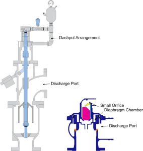
Fig 4. Hydraulically Controlled (Diaphragm) Air Valve – On the left is an American Hydraulically controlled air valve design utilising a dashpot arrangement to regulate closure. On the right is a Hydraulically controlled diaphragm air valve utilising the principle of equal pressure and differential area in the diaphragm chamber to regulate closure. Both designs dump water before closure. The volume of water dumped is dependant on the closure time of the valve, the size of the valve and the differential pressure across the valve’s outlet.
AirFlo Variable Orifice Air Valve Technology
Empirical research confirms in over a decade of results conducted by several researchers on a variety of conditions, that the most critical factor that determines the creation of Surge and Waterhammer on closure of the large orifice of an Air Valve, or the prevention thereof, is the size of the orifice at that critical point before closure. This is regardless of whether the system on which the Air Valves are employed is a gravity fed main or pumping system as the surge and waterhammer phenomena occur during initial filling as well as during column separation and the subsequent rejoining of water columns.
However, research and extensive computer modeling also indicates that the size of the orifice has to be balanced with the conditions within the pipeline system as too small an orifice may dampen Waterhammer but increase mass oscillation (surge) as well as increase filling times for a pipeline whilst too large an orifice will induce Waterhammer.
The demand for an air valve design with a multi adjustable orifice to address the above has been understood as far back as the early 1980’s but, no successful, practical commercially produced air valve was designed until the advent of AirFlo Variable Air Valve Technology.
AirFlo Variable Orifice Air Valves incorporate a Variable floating shuttle that automatically adjusts the discharge outlet of the valve to the conditions within the pipeline and provides the optimum orifice diameter at any given point during the performance of the pipeline to ensure effective air release whilst preventing Waterhammer and substantially reducing mass oscillation.
AirFlo Variable Orifice Air Valve Technology is a 100% South African developed and patented technology that represents a revolutionary way in the addressing of Surge and Waterhammer during the release of air. This technology effectively breaks away from the drawbacks and constraints of the surge damping function of other air valve technologies.
The most significant advancement is the fact that this design does not have a stationary and standardised orifice and is sensitive to the air outflows of the pipeline. This smooth transition from one differential pressure to the next and the constant adjustment of the orifice size and therefore the backpressure and the slowing down to the advancing water column as the outflow velocities increases is of major benefit to the pipeline designer as it takes away the guess work of whether the orifice is either too small or too large under varying pipeline operating conditions.
The action of the AirFlo Variable Orifice is such that it will readjust itself under pump trip and column separation conditions thereby allowing for effective air release whilst reducing the magnitude of the Surge as well as reducing the amplitude and time period of the pressure wave. This brings the pipeline to a steady state much more rapidly and smoothly without damage to system.
AirFlo Variable Orifice Air Valve Technology is advancement into Air Valve technology and has moved the performance criteria and the technology for air valves ahead in a significant way in essence setting the bench mark for measuring future advancements in air valve technologies.
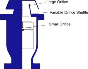
Fig 4. Variable Orifice Air Valve – AirFlo Variable Orifice air valve indicating the variable orifice shuttle which automatically adjusts the air discharge to suit pipeline operating conditions and prevent Surge and Waterhammer. The valve also allows unrestricted air intake under vacuum conditions and pressurized air discharge under pipeline operating conditions.
Modelling Air Valves in Surge Analysis Software Programmes
The accuracy of surge analysis has significantly increased as computer capacity and the sharing of research in specific areas have advanced. However, the accuracy of a surge model is highly dependant on the quality of the data, the capability of the software and the understanding by the modeller of these destructive phenomena and the pipeline components utilised to prevent or reduce their impact. The end result of an analysis should be the combination of these factors to deliver a result that is a close approximation of the real world.
Every air valve design has a different characteristic in terms of performance, and it is important that the selected design is correctly modelled to reflect the reality of the design being utilised.
There are several commercially available computer packages that accurately take into account the performance of conventional Air Valves, Non Return Air Valves and Anti Slam Air Valves (3 stage air valves). To model the first two designs have become easier with time as software developers allow for the insertion of the intake orifice and the discharge orifice and the software will then accurately model the valve. However, anti slam (3 stage air valves) are sometimes inaccurately modelled. The reason for this is the assumption that the small orifice also provides part of the surge protection benefit. This assumption is incorrect as the physics of the valve, under surge conditions, only allows for a throttling effect through the anti slam or anti shock orifice.
The magnitude of impact through this inaccurate assumption can be significant. A DN80 anti slam valve with a 1.5mm diameter small orifice and an anti slam orifice of 15mm in diameter will result in a 1000% inaccuracy in size and therefore a significant error between utilising the anti shock orifice as a modeller should or utilising the small orifice which is incorrect. This implies that the resultant surge analysis model whilst impressive could be a misrepresentation of what may occur in the pipeline in reality.
Conclusion.
Research into air valve technologies indicates spurts of innovation followed by periods of stagnation. It also indicates that technologies evolve in interesting ways and the misconception that design acceptance follows an evolutionary path of one successful design succeeding the next is not necessarily true as several technologies run parallel to each other even though there may be substantial empirical data for one technology to supersede another. This peculiarity may exist due to several dynamic market forces and historical reasons.
Air Valve technology as it stands now indicates that even some of the more commercially successful designs are not superior from all points of view and have inherent limitations and that pedigree in age does not necessarily reflect pedigree in performance.
This article briefly touches on the important aspect of the surge damping function in Air Valves and gives a broad guideline on how this feature functions in the different available air valve designs arming decision makers with a wider scope of knowledge in this often specialised but critical area of pipeline design and component selection.
The article also indicates that surge damping in air valves is a major challenge and that the governing factor, supported by extensive research is the size of the orifice at the point when the air valve closes. The better the ability, to govern the orifice under all operating conditions, the better the protection the air valve provides. AirFlo Variable Orifice Air Valve Technology is the closest in technologies that provides protection in a wider operating range and therefore may constitute better pipeline protection.
Pipeline design and operation has become more complex with time. Conversely, it is important to seek out less complicated and user friendly technologies that will provide years of maintenance free operation. AirFlo Variable Orifice Air Valve Technology again is one such technology that provides uncomplicated long term performance.
Air valve design selection is extremely important to pipeline performance. It is the author’s sincere wish that this article will contribute to the better understanding of the available air valve designs on the market and the important role they play in either inducing or preventing surge and waterhammer.
About the Author:
Allistair P. Balutto comes from a petrochemical and mechanical engineering, marketing and entrepreneurial background and has been involved in the Fluid Conveyance Industry for more than 30 years.
He holds patents in valve design and, has in the last 30 years developed and co-developed several successful products, markets and business concepts and, has been instrumental in setting up some of the most successful and award-winning products in the Fluid Conveyance market in this period.
Allistair has lectured extensively on Pipeline Engineering, Business Management and Market trends and has authored several technical papers and publications on Hydraulic Design and Valve Engineering principles and general Pipeline Design. Some of his writings are globally referenced and has become part of the syllabi of learning institutions.