Variable Orifice Air Valves vs Anti-Shock Air Valves
Perhaps I should start off with a confession.
The confession is this; I was part of the Anti-Shock development team in the 1990’s and for many years led this technology locally and globally in both a Technical and Marketing capacity and, through seminars and technical writings. These writings and the research conducted, and observation made then, is still today referenced in many Air Valve Research papers and other writings.
I was also part of a small and dynamic team that developed the AirFlo Variable Orifice Air Valve Technology in 2010. This technology was developed out of the years of research and observations of the Anti-Shock Air Valve and many of other air valve designs in situ, in literature and in testing facilities. Through these tests, interactions and observations, we saw what worked but tackled that which did not work effectively resulting in the AirFlo Variable Orifice design as manufactured currently.
The Anti-Shock design was appropriate for its time in that it was substantially better than the older Kinetic air valves. However, in its original patent, the Anti-Shock device was meant to be a multi orifice design with each orifice “switching” to a progressively smaller orifice in tandem with the change in the differential pressure across the large orifice. This was commercially unviable because the valve would be substantially taller and much more complex and expensive. This vision of a multi orifice design with the orifice size changing in line with the differential pressure across the large orifice is exactly what the Variable Orifice design has achieved through its patented technology.
The Variable Orifice Technology has proven its efficacy and performance on the largest pipelines in South Africa and is exported to several countries around the world.
We are often asked, what is the difference between the two designs. Our simple and honest response is that the Variable Orifice design is the latest in the evolution of Air Valve technology and is superior in performance and much better in Surge and Waterhammer protection to the Anti-Shock design. This statement is based on rigorous testing carried out over 28 years of research by designers who have worked on the development of both technologies.
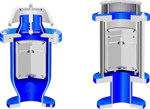
Fig. 1 AirFlo Variable Orifice Air Valve and Anti-Shock Air Valve – On the left-hand side is the AirFlo Variable Orifice Air Valve patented 2010 with larger flow areas, better Surge and Vacuum protection. AirFlo Anti-Shock Air Valve with Stainless Steel barrel patented 1994.
How and Why Does Variable Orifice Technology Differ from Anti-Shock Air Valves?
Variable Orifice Air Valves are distinctive from Anti-Shock Air Valves on several levels. These include:
Body Design – Form meets Function vs Function being fitted into a pre-determined form
AirFlo Variable Orifice Air Valves have a distinctive body design, more squat, with a wider body and an intentionally designed internal flow path that provides a low headloss across the valve without compromising the effective surge and vacuum function of the valve. This is a classic case of form meeting function.
Anti-Shock Air Valves with Stainless Steel barrels are manufactured in off the shelf, Stainless Steel pipe with a set internal diameter. The valve therefore has an inefficient flow path (specifically for sizes DN100 and larger) and a higher headloss in comparison to the Variable Orifice design. The inefficiency is increased in designs where the tie rod is utilised as both a guide and tie rod.
The AirFlo Variable Orifice air Valve is dependant on size, between 7% and 23% more efficient than a standard Anti-Shock Air Valve design and, up to 37% more efficient than more recent designs where the tie rods are located within the barrel.
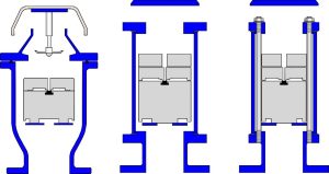
Fig. 2 AirFlo Variable Orifice Air Valve with Two Types of Anti-Shock Air Valves – On the Right is the Variable Orifice Air Valve with purposefully designed body shape to increase Surge protection and Discharge and Intake efficiencies. In the middle is the standard Anti- Shock Air Valve with Stainless Steel Barrel where performance is restricted by the diameter of the barrel by 7% to 23% in comparison to the Variable Orifice design. On the left is the newer Anti- Shock Air Valve with Tie Rods housed within the barrel. This restricts performance by up to 37% in comparison to the AirFlo Variable Orifice design
Surge and Waterhammer Protection – Infinite vs Partial Protection
The AirFlo Variable Orifice patented design has a non-pressure bearing, adjustable floating orifice (Variable Orifice) that, automatically adjusts the outlet of the air valve in accordance with the velocity within the pipeline thereby assuring surge protection regardless of the flow rate within the pipeline. Test results indicate superior Variable Orifice Valve provide superior Surge protection than Anti-Shock designs under equal operating conditions.
Anti-Shock Air Valves have a pressure bearing surge damping device with a static orifice size that is reliant on a “Switching Point” in order to activate the surge protection capabilities.
If the Anti-Shock Orifice is activated at a very low differential pressure across the large orifice, then, the design may prevent Waterhammer but result in Surge (mass oscillation). In addition, activating the device at low differential pressures increases the filling times of the pipeline substantially.
If the Anti-Shock Orifice is activated at too high a differential pressure, then it will induce Waterhammer. In addition, research indicates that the so called “Switching Point” (the point at which this device is activated) differs for different size valves.
If the Anti-Shock Orifice is not activated at all then the valve will behave like a Kinetic Air Valve and induce Waterhammer on closure. There are several reasons why the device may not be activated.
Reasons include:
- Sizing too many air valves on a pipeline, a problem that is common when the Design Engineer uses the manufacturers air valve sizing and design software indiscriminately.
- Sizing only on the vacuum function and not looking at the overall function of the air valve across the operating cycle of the pipeline.
- Standardizing on the valve size on a pipeline to minimize future maintenance problems. This implies that some air valves may be oversized for discharge. In these cases, the differential pressure may not be high enough across the large orifice to activate the Surge damping device thereby still creating Waterhammer on closure of the air valve.
Vacuum Protection – An Air Valve is Measured on Efficiency of Vacuum Protection
Vacuum protection is the most critical of all air valve functions. Tests clearly indicate that the Variable Orifice design, due to its unique profile, allows a greater capacity of air intake than Anti-Shock valves under the same operating conditions. The variance where, the Variable Orifice intake capacity is greater than the Anti-Shock design, can vary depending on the size range, between 7% and 37%.
The reasons for the differences between the intake capacities between Variable Orifice Air Valves and Anti-Shock Air Valves are due to:
- Body design – where the Variable Orifice design profile and internal configuration is purposefully designed for better performance vs the Anti-Shock Air Valve which is constrained by its housing.
- Partial closure of the large orifice – by the hovering of the Anti-Shock float which, throttles air intake. This phenomenon also known as a “Venturi Effect” is more prominent in designs where the “Switching Point” is at a lower differential pressure.
Performance Testing vs Published Data – Theory Can Not Be a Substitute for 3rdParty Testing
Our approach to Air Valve design is born out of the understanding that an Air Valve is a highly complex device and the only and best form of validating an Air Valve’s design performance is through 3rd Party Performance Testing. No theoretical modelling will sufficiently highlight the intricacies and peculiarities that slight changes in length, diameter, flow paths and other factors in the design makeup.
The performance of the Variable Orifice design and our own Anti-Shock air valves was subjected to 3rd party testing by the South African Bureau of Standard (SABS) in 2012 and again in 2013 where we also conducted comparative testing on 17 air valve designs (SABS Tests Ref. 12H050 and 13H197).
These tests indicate that some Air Valve manufacturers have overstated their air valve intake performance by more than 50%. The overstating of air valve performance by some Air Valve manufacturers are confirmed by our research in South Africa as well as research from some prominent universities in Spain, Canada and South America over the past 10 years.
A last and critical point on the performance characteristic of the Anti-Shock design is the question of why the performance figures of the valve is exaggerated. The answer is somewhat straightforward and complex at the same time. The straightforward answer is Convergence! Manufacturers will converge on a particular shape, manufacturing process or performance of a product based on the popularity of a particular design. However, having converged on a particular design, the question is how to differentiate between manufacturers. The first and most obvious is price, the second is trim and materials that are not present in the original design. The last and most worrying is by claiming superior performance even if the one is almost clone of the next. It is the last point which some manufacturers seem to have chosen as the marketing path.
There may be an additional factor. There are two seminal technical papers in the Air Valve industry that mentions that the average Discharge Co-efficient (Cd) factor of an Air Valve should be 0.62. These technical papers make a reasonable assumption specifically for the discharge of a Kinetic air valve. In fact, tests reveal that some air valves can have Cd factors of up to 0.69 for air intake and some as low 0.07 with the average intake being well below the 0.62 predicted by these two technical papers who have calculated the air valve’s performance as an orifice and not the complex hydro-pneumatic device that air valves are.
Manufacturers who have not invested in practical 3rd party Air Valve testing either due to cost or available equipment, have utilised figures from these two and other similar technical papers and/or standard orifice calculations to extract their performance figures. However, these manufacturers’ published figures differ substantially to actual 3rd party tested performance results. This is because an Air Valve is not a simple orifice plate but a complex device and minute changes in height, float weight, position of components can have a dramatic and often negative impact on the valve. With regards to the Anti Shock Air Valve design (specifically the Stainless-Steel barrel type). There are three important 3rd party tests conducted which were carried out in 1996, 2005 and 2013 on the original Anti-Shock Air Valve design. These tests provide similar results yet, the published data of virtual clones of the original design with the same body diameter and virtually the same overall height and internal arrangement claim discharge figures substantially higher than the original Anti-Shock design with no proof of any 3rd party testing having been conducted.
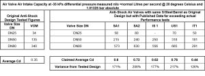
Figure 3 – Comparison of Published figures between Different Anti-Shock Air Valve manufacturers utilising the same Stainless Steel Barrel Design with Similar Dimensions and Weights but vastly claimed performance figures.
The Table indicates firstly the average intake performance figures obtained from three 3rd Party Tests on the Original Anti-Shock Air Valve. These Tests include: Nash Vacuum Pumps test- 1994, CSIR DPSS 2007/144 and SABS Ref 13H197.
The table also indicates five different manufacturers from South Africa and other countries around the world with virtually the same design but substantially different published figures. Of the five manufacturers, the author is only aware of one manufacturer who has carried out actual testing for both intake and discharge testing. However, the intake tests were conducted without the Anti-Shock float because the float partially lifts under vacuum conditions closing the large orifice and therefore the Cd factor changes dramatically as proven in other 3rd party testing. Some of these designs for this reason are sold as Kinetic Air Valves where the control float and small orifice float is linked to prevent premature closure,
Conclusion
AirFlo Variable Orifice Technology is an advancement on Anti-Shock air valves. This fact has been proven by 3rd party testing and attested for by the performance of these valves on some of the largest pipelines locally and several countries internationally.
The purpose of this short document is to point out the difference of the two designs and in the process show that the Variable Orifice Air Valve is the next step in an evolutionary process, in the development of Air Valve technology.
A more important point that this document highlights is that there are several manufacturers who have converged on the manufacture of Anti-Shock air valves in the original stainless steel barrel design since the collapse of the patent of this product. However, to stand out in the market many have published theoretical performance figures that far exceeds the capacity of the design. This should be concerning to the designer as the margin of error between actual performance and published data may vary between 26% and 106% and may put a pipeline at risk
With the Variable Orifice design, the design engineer can reference our performance data with confidence and be assured that their pipelines perform as intended.
Allistair Balutto 2022 (c)